
TB-302 : FPSC- Troubleshooting Guide
*Trouble Shooting:
The Aeromotive FPSC has built-in safeguards to protect itself and the engine. The integrated processor on the circuit board is programmed to continuously monitor basic conditions and operating parameters; current draw, available voltage and RPM input for example. If one of these parameters exceeds its operating limit, the FPSC defaults into self protect mode, shutting itself and the pump down. Whenever this occurs, all LED indicator lights on the FPSC will flash in unison.
Note: When power is removed from the IGN/PWR terminal (activation terminal) the FPSC LEDs will extinguish and the unit will reset. When power is reapplied, the unit will function normally until the fault condition reoccurs. If the fuel pump shuts off unexpectedly, and you wish to know whether the FPSC has entered "self protect" mode, check the status of the LED lights before turning off the ignition, or the fuel pump run switch.
Symptoms of common installation problems are outlined below, followed by detailed solutions for each. Go to the appropriate solution by clicking on the symptom, or scrolling down to the solution with the same number.
1) The yellow "TACH" LED won't flash when the engine runs and/or the green "FULL" will not illuminate at the set RPM.
2) The "FULL" light flashes randomly at idle, causing the pump to surge, and/or default shutdown occurs while driving.
3) The fuel pump primes with "key-on" but a default shutdown occurs when attempting to crank or start the engine.
4) The pump performs inconsistently and/or does not speed up and down or doesn't deliver full flow at "FULL" speed.
5) The pump seems to run slow at full speed or in manual override and the red "STALL" light is illuminated.
1) The correct, 12-V, square wave tach signal is not connected to the TACH terminal on the FPSC.
Without the correct tach signal the FPSC can't read engine RPM, preventing it from varying the speed of the pump with engine RPM. The Yellow "TACH" light may not flash, and/or the pump speed may not change with RPM. When the tach signal is incorrect or corrupted, the FPSC will not work, and it may shut itself and the pump off to protect the engine.
The tach reference required is described as a Square Wave, DC, 0-12V tach signal (with a dwell angle of 50ns and the ability to support current draw of 100 milliamps). This is a standard RPM signal that's been around since the early days of internal combustion engines. It's commonly used to drive aftermarket tachometers and is available at the coil- negative terminal of conventional, single-coil, 4-6-8 cylinder engines with a “points” style distributor.
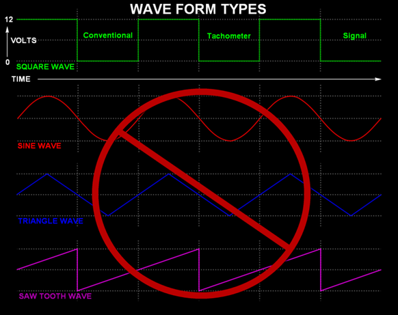
Today's modern, multi-coil or coil-on-plug ignitions may be harder to work with as they cannot provide adequate signal and/or frequency from any one coil to generate a tach signal able to operate the FPSC. For these applications a "Tach Adapter" is often used to pull the individual coil events together and generate the proper, square-wave signal. Tach adapters are available from several manufacturers including:
MSD P/N 8913
Autometer P/N 9117
Dakota Digital P/Ns SGI-5 and STA-1000.
Warning: Do not use the negative coil terminal on a “multi-strike discharge” ignition such as that from an MSD box. The "multi strike" output generates a false-fast signal, use the tach-out lead on the MSD instead.
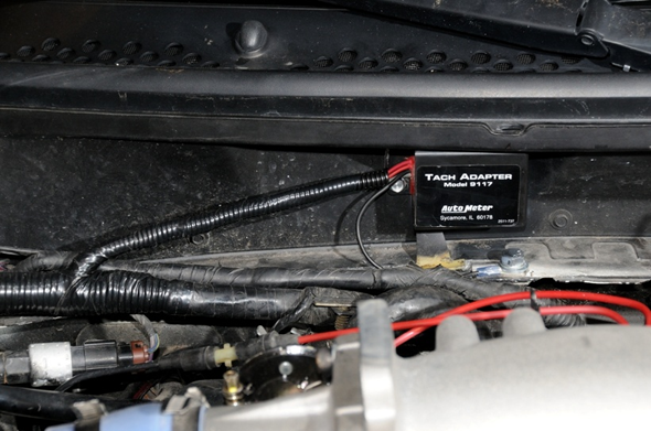
One of today's most popular performance platforms involves the GM LS engine, whether in the OEM chassis or transplanted into a wide variety of popular muscle cars. Often the OEM Powertrain Control Module (PCM) is used to control the engines EFI and ignition system. Like most modern EFI engines, the LS platform uses a coil-on-plug ignition system, making a good, square wave tach signal with sufficient frequency unavailable at any single coil.
A tach adapter can work well on any COP ignition, including on the LS engine, but in LS applications where the OEM PCM will be retained, there is another possible source. The factory PCM does have a tach output signal, and it is a square wave type, but it's 0-5 Volts instead of the 0-12 Volts needed. Close, but no cigar, at least not without some creative wiring...
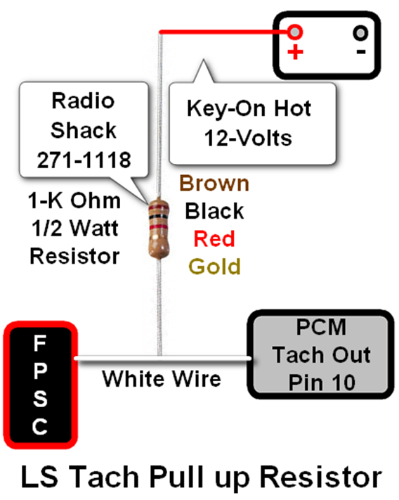
Using a resistor, wired in what's called a "pull up" configuration, it's possible to raise the high side of the OEM tach signal from 5-Volts to 12-Volts. In simple terms, we're supplying 12-Volts to the tach signal provided by the PCM through a resistor, which acts to "pull up" the voltage from 5-Volts to 12-Volts. Normally, a resistor like that shown in the diagram, is sufficient to bring the tach voltage high enough to operate a standard tachometer or the Aeromotive P/N 16306 Fuel Pump Speed Controller (FPSC).
The resistor shown in the diagram is readily available from Radio Shack. Here is a link that should take you to their website where they can be ordered:
http://www.radioshack.com/1k-ohm-1-2w-5-carbon-film-resistor-pk-5/2711118.html#.VK9RAXuDMk4
What if a good, clean tach signal just isn't available, or you don't want to control pump speed progressively? There’s an alternative, but it does turn the FPSC into a simple, two-step speed controller, with a straight low output, switched to high. Here the low-voltage must be set high enough to support up to medium load driving (10-11 Volts) and full speed is triggered in one step, at high load.
This requires a vacuum or boost Hobbs switch be installed in the intake manifold and uses the manual override circuit to activate full-speed. The manual override terminal on the FPSC requires a ground connection to activate. Manual override activation is normally done by closing a toggle switched to ground, but with a little ingenuity, full pump speed using the manual override circuit may also be automated using a pressure sensing Hobbs switch.
There are several pressure-sensing switch options, including a boost switch that turns on (closes) with boost, or a vacuum switch that turns off (opens) with vacuum. Between a vacuum and boost activated Hobbs switch, which is best? The vacuum switch is safer, faster and more flexible, working equally well installed in the intake plenum of both naturally aspirated and boosted engines.
The ideal Vacuum Switch will have a low threshold, between 2-3" HG, keeping the pump slow during light load-cruise and mild acceleration while providing full pump speed before high engine load can develop. A vacuum Hobbs is also safer than a boost switch, switching to full speed before boost builds in the intake. Plus, if a pressure switch fails it typically fails in the "normal" position. A boost switch is "normally open", so if it fails, it fails to close and the pump stays at low speed all the time. A vacuum switch is "normally closed", so if it fails, it fails to open, leaving the pump in full speed all the time Vapor lock on a hot day is inconvenient, but detonation can be far more frustrating and expensive.
Finding a quality vacuum switch can be tricky. Industrial suppliers are typically a good resource but not all will sell to the general public. Here's a link to Digikey's website. They are an "industrial supply" class company that does sell to commercial and retail customers. Copy and paste or type this link into your web browser address bar for more information, including specifications, pricing and availability, it will take you directly to the correct product page.
Vacuum Hobbs Switch from Digikey Corp:
http://www.digikey.com/product-detail/en/77343-02.0HG-01/480-2060-ND/1162790

2.) The TACH signal is corrupted or "dirty" due to signal noise or EMI (electro-magnetic interference).
If an EMI problem, or a corrupted tach signal is present the FPSC cannot correctly identify engine RPM, causing the pump to surge randomly, flashing the green "FULL" light at idle and low engine speeds. If you suspect tach signal noise, check to see if the "FULL" light is randomly flashing at idle, or pull the tach lead and drive light load but varying RPM up and down to see if a default shutdown still occurs. Always confirm a default shut down by checking if all LED lights are flashing before switching power off to the pump
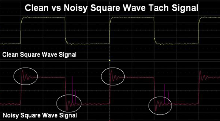
As long as we have a legitimate 12-Volt, Square Wave Tach Signal to start with, EMI noise problems may be avoided by rerouting the tach signal wire by itself, away from other components or wires in the wiring harness. Other wires could be inducing signal noise into the tach wire.
When an aftermarket tachometer is installed and shares the same tach signal as the FPSC, it may back-feed signal noise into the circuit. In this case route the tach wire from the ignition box (or tach adapter) to the FPSC first and then from the FPSC to the tachometer.
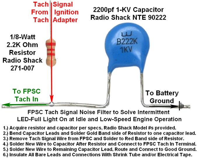
If signal noise persists, a simple EMI noise filter can be constructed using a resistor and a capacitor, as illustrated in the diagram at right. This combination has proven very effective in filtering down excessive noise to a minimum, providing a usable signal, if needed.
The hyperlinks below can be copied and pasted to your browser address bar, they are direct to the product's page:
Radio Shack 2200pf 1KV Ceramic Disc Capacitor:
http://www.radioshack.com/nte-90222-cap-cer-disc-2200pf-1kv/55047614.html#.VJ8gi_8MAA
Radio Shack 1/8-Watt 2.2K Ohm Resistor:
3.) Supply voltage to the FPSC terminal(s) marked IGN/PWR and/or BAT fall below 9-volts during operation.
To function correctly, the Aeromotive FPSC requires a stable, 12-Volt DC power supply be connected to the on-board processor at all times during operation. The FPSC monitors system voltage on the IGN PWR terminal (commonly referred to as the trigger terminal), and the BAT terminal. For the fuel system to prime and the engine to start and run properly, the fuel pump must run when the key is in both the "run" and the "crank" positions. The IGN terminal on most ignition switches will ensure this, however excessive components wired to the IGN terminal often result in an overload of the ignition switch. The result is a drop in voltage through the switch that can cause a default shutdown of the FPSC.
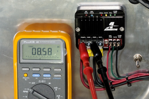
During startup, the electrical system experiences the highest load and the lowest voltage to all electrical components. For the engine to start reliably, it's critical the battery is fully charged, in good operating condition, and that the FPSC is wired correctly. System voltage falls in crank, if it goes below 9-V DC at the “IGN PWR” or "BAT" terminals the FPSC it may trigger a default shut down, preventing the engine from starting. Voltage measured at the FPSC during crank will reveal if this is a problem.
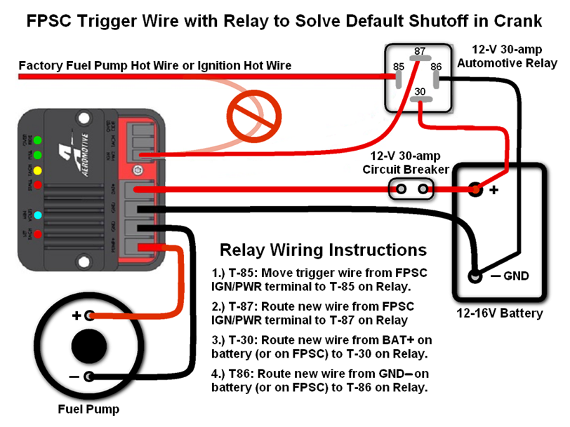
If ignition the circuit is overloaded, or a stable 12-volt trigger for the IGN/PWR terminal cannot be found, install a relay on the “IGN PWR” circuit. This allows a weak trigger signal to activate relay (which is less sensitive to voltage drop) that will then direct full battery power to the IGN/PWR terminal on the FPSC.
Examine the schematic below for a detailed look at how to install a relay for the FPSC trigger terminal. Note the problem circuit is removed from the “IGN PWR” terminal and connected to the relay activation terminal instead. The relay uses an electro magnet component instead of a computer to operate, which is less affected by voltage a voltage drop, providing direct BAT voltage to the IGN/PWR terminal, ensuring the highest system voltage available is provided to the FPSC.
4.) Ground wiring for the FPSC is not made per instructions, or wire terminal ends and/or splices are faulty.
The Aeromotive FPSC ground circuit must be routed per the installation instructions. Failure to do so may result in the unit defaulting into self protect mode. The FPSC uses a frequency of on-off to drive the speed of the fuel pump. This is also referred to as PWM or “pulse width modulation” motor-drive control. The frequency of on-off is so rapid that the pump never seems to actually shut off, but the pump speed is effectively varied up and down without harming the motor.
Correct wiring of the FPSC includes particular attention to the ground circuit, including that of the fuel pump and the FPSC. The new generation Aeromotive FPSC, P/N 16306, incorporates a ground terminal for the unit itself, and for the fuel pump.
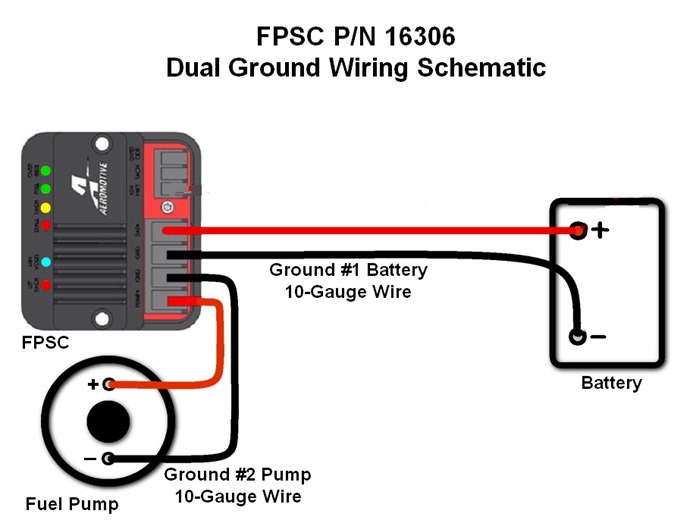
In order to ensure a proper, matching ground path for both the pump and the controller, it is necessary to route the provided 10-gauge wire from the fuel pump to one of the two FPSC ground terminals. Then, route a suitable 10-gauge ground wire from the FPSC to the battery ground cable (either end of that cable, at the battery or at the chassis is an acceptable connection point). This ensures that the path to ground for both the fuel pump and the FPSC have equal (and minimal) resistance and that the FPSC will be able to properly control pump speed.
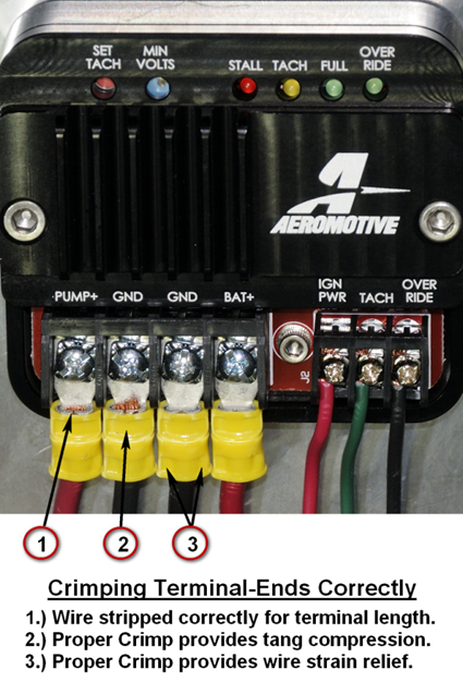
Poorly crimped or soldered wire connections and terminal ends are critical to if the current required to run the pump at full speed is to be able to flow to the motor. Correctly crimping or soldering terminal ends to a wire requires both the correct gauge terminal ends for the wire and proper tools to complete the job. Done right, crimped connections can be just as effective and durable as soldered connections.
For Crimping terminal ends a compound crimp pliers with the appropriate jaws for the style of terminal provide excellent results.
Recommended Crimping Tools
MSD Crimp Tool: P/N 35051
MSD AMP Lug Jaws: P/N 3507
Soldered connections are considered the ultimate electrical connection by many, but this is true only if soldering is done correctly. Use a butane torch or soldering iron and quality, rosin core solder. All soldered connections require insulation with suitable shrink tubing. Correct tools for effective soldering may be found noted below:
Recommended Soldering Tools
Blazer Micro Torch: P/N GB2001
Kester 44 Rosin Core Solder 60/40 .031 1 lb. Spool
5.) Current draw through the FPSC has exceeded design limitations, causing the "STALL" light to illuminate.
The Aeromotive Fuel Pump Speed Controller is engineered as a heavy-duty power supply, capable of supporting modern, high flow electric fuel pumps that can draw up to 25-amps continuously. It is not suitable for a fuel pump or pumps that will exceed 30-amps continuous current draw, or for applications where peak current draw exceeds 40-amps. If the red "STALL" LED illuminates, find the cause of excess current draw before continuing use.
WARNING: Operating the Aeromotive P/N 16306 Fuel Pump Speed Controller in applications that illuminate the “STALL” light may result in excessive heat, poor fuel pump performance and damage to the FPSC itself.
If the pump being run by the FPSC has not previously created excessive current draw, illuminating the “STALL” LED, check for flow restrictions after the fuel pump, including and especially any fine, post filters located downstream. A clogged post filter can create extreme fuel pump pressure and attending high current draw. Systems employing large, high flow fuel pumps, can experience enough back pressure to drive current draw above and beyond acceptable limits.